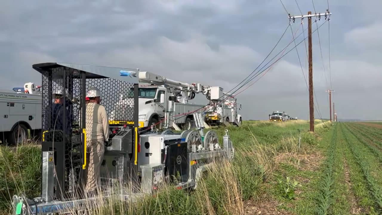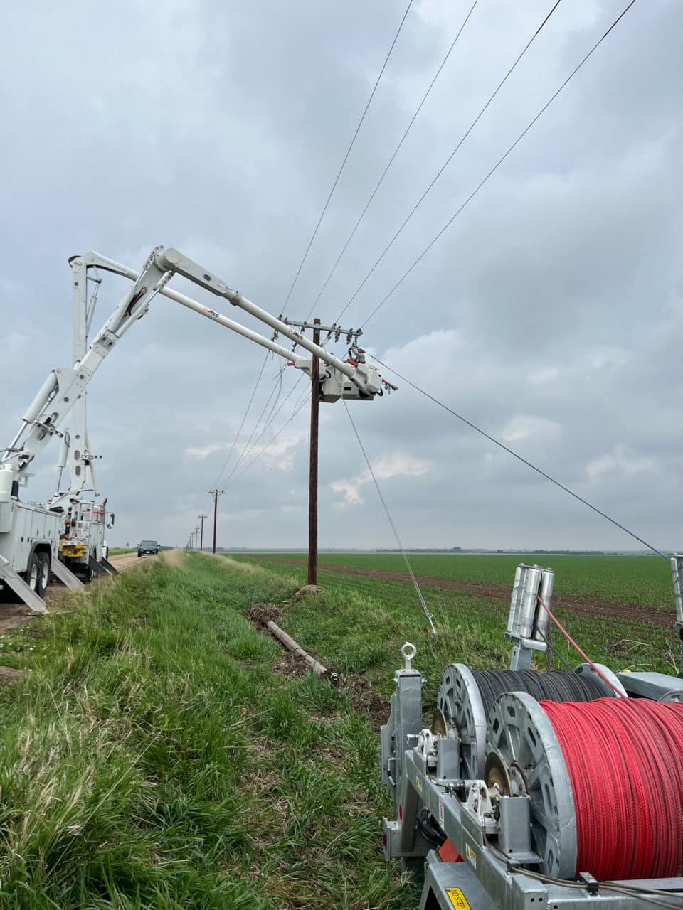
The main objective when stringing overhead distribution is to install the conductor from one point to the other in the best possible condition and in the safest, most economical manner. To accomplish this job, the proper equipment, tools, and training are essential.
Four Key Components
There are four key operating components used in an overhead distribution stringing job: the tensioner, pulling line (bull line), stringing blocks, and the puller. These key pieces should work together, and if any one of these components is deficient, either in design or performance, it directly affects the other three. For example, if the stringing blocks are of poor quality and do not roll efficiently, then they directly affect the amount of pulling capacity needed to install the conductor. This would then require a larger capacity puller.
The pulling line can also be affected by the other components. For instance, if they are low-quality or undersized, they can increase the load beyond the line’s safe working limit, potentially causing it to fail. The tensioner will also be required to create more tension, thus causing additional stress on the hardware, structures, and the most important component - the conductor. All four components work together, and one deficiency can cause multiple potential problems.
Selecting the appropriate equipment for your operation is essential for stringing success. The first step in the selecting the equipment is to utilize the Institute of Electrical and Electronics Engineers (IEEE) guide formulas to determine the amount of tension it takes to pull the conductor in with adequate capability and some reserve. There are two formulas used. The first formula, T1, is used to establish the amount of tension required to support the conductor in one span. The second formula, TMax, is used to determine the maximum amount of tension that is needed to pull the conductor in.
Tension Formulas
T1 = the tension required to support 1 span (static condition)
W = weight per unit length of the conductor
L = span length
D = sag during the stringing phase
TMax = the maximum tension required to pull the conductor
.98 = efficiency of stringing blocks
n = number of supports or blocks
T1 = WL2 ÷ 8D
TMax = T1 ÷ .98n
Equipment
The tensioner—a single trailer designed to support the conductor reel's size and weight—should also include multi-groove bullwheels to tension the conductor without feeding it directly from the reel. However, if the reel can safely handle the required tensions, a hydraulically-controlled puller/tensioner offers a practical and effective solution, taking into account the reel’s physical condition.
Secondly, while some countries use bullwheel-type pullers for different reasons, using two similar machines called ‘puller/tensioners’ together offers better control and a smoother installation. In the United States, it is more common to use a drum-type puller with a large winch for pulling line or bull line. Traditionally, the use of a parallel-lay rope, like Uniline™, with little elongation and a high strength-to-size ratio, should be used on drum-type pullers.

The third piece of equipment used in distribution operations is commonly referred to as a ‘block’, though there are several other industry references for this product. High-quality stringing blocks use ball bearings to allow the sheave to spin efficiently, usually at only a 2% loss per block. The minimal loss is due to the constant bending and straightening of the conductor as it passes over the blocks. It is common to use a larger diameter block at the lead and dead-end poles, and at severe angle points in a pull. The stringing blocks are usually installed when framing the poles, crossarms, hardware, and insulators.
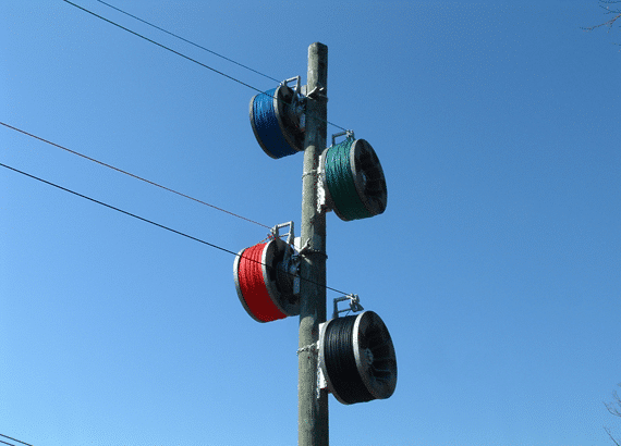
Once the poles on the jobsite have been installed, a pilot line system, like the Sherman+Reilly Spider® System, can be placed on the pole at the conductor tension end of the pull. The Spider System consists of a braking controller, four storage reels, Spiderflex rope, and accessories. Spider System braking controllers can be chained to the lead pole and its reels, depending on the model, can support 3,000 or 6,000 feet of pilot line. The four ropes can be taken from pole to pole as they are framed with distribution blocks. When the last pole is framed, there will be four continuous ropes of different color from one end of the pull to the other. Using this system instead of individual threader ropes allows the pulling line to be pulled back individually, one at a time, to string the phase conductors and finally the neutral. The Spider System also allows the main pulling rope to be strung under tension, keeping it clear from underbuild or other obstructions below.
Whether you use a Spider Pilot Line System or another method, once the pulling rope is installed and attached to the conductor with a grip and swivel, each phase can be pulled through individually, caught off, and brought up to sag as the pulling rope is returned to the tensioner for the second pull. Once the three-phase conductors have been pulled and sagged, the neutral can be pulled in the same way, completing installation of the conductor. All that remains is the clamping-in of the conductors into the insulators and removal of the stringing blocks to finish the job.

Need some guidance for your crew or maintenance team? Sherman+Reilly provides in-service, classroom, and on-site training customized for your equipment and your team from operations to preventative maintenance. Contact us at 423-756-5300 or click below to learn more about our training options.
Learn more about how to pull conductor with a four drum rope rig by watching our whiteboard video. Click below to go to our YouTube channel:
