Home | Stringing Blocks and Accessories: Transmission | 70 Series Transmission Bundle Blocks
70 Series Transmission Bundle Blocks
TRANSMISSION BUNDLE BLOCKS
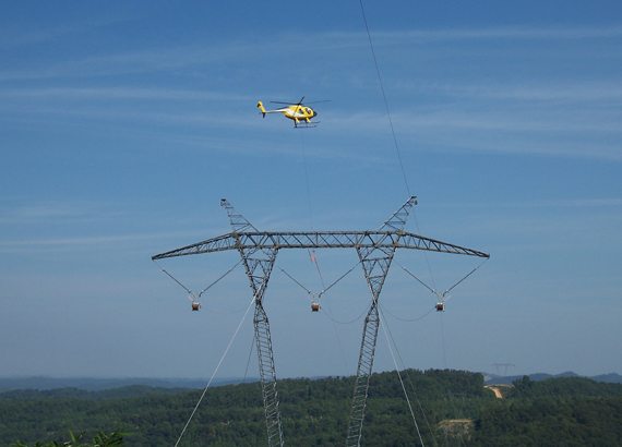
Transmission class line construction is very specialized. Terrain, spans, structures and pulls are all larger and the conductor can require a plethora of construction configurations. The transmission bundle block configurations can range from single to bundles of two, three, four or six per phase. For all these reasons, the configuration and quality of the blocks which interface with the conductor are of the utmost importance.
KEY FEATURES
DESIGN
Ideal for versatile field reconfiguration to meet the demands of changing stringing needs and conditions.
SIZING
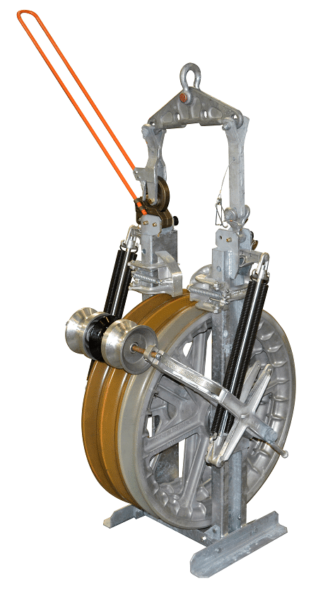
Meeting the vast range of transmission conductors with with 20″, 22″, 28″, 35”, and 42″ (OD) sheaves.
CONFIGURATION
Rigid frames made up of hot-dipped galvanized steel are available in 3 designs: symmetrical, slimline, or offset. Bundle blocks are available in 2, 3, 4, and 6-conductor configurations.
OPTIONS
Available block grounds and helicopter options.

SPECIFICATIONS
ALL SPECIFICATIONS
70 SERIES TRANSMISSION BUNDLE BLOCKS
OVERVIEW
About Transmission Construction
Transmission-class line construction is very specialized. Compared to distribution construction, structures are taller, spans are longer, conductors are larger/heavier/stiffer, and pulls are longer and can extend over steep and very uneven terrain. In addition, aluminum conductors vary in construction requirements, calling for special handling techniques, tools, and equipment.
Transmission construction also involves different line and structure designs, as well as different conductor configurations (including simultaneous stringing of multiple conductors (‘bundles”) using a single pulling line). These configurations can range from single to bundles of two, three, four, and six conductors per phase. Some lines are strung using conventional, ground-based equipment and tools, while others require stringing using helicopters.
For all these reasons, the configuration and quality of the blocks in which sheaves are mounted are as important as the sheaves.
About 70 Series Transmission Blocks
The 70 Series single-conductor stringing blocks are an ideal choice for simultaneous stringing of multiple large-diameter transmission-class conductors. These blocks are the result of extensive field research, laboratory testing, and real-world experience over a period of 75+ years. With some exceptions, 70 Series blocks are available in two, three, four, and six-conductor configurations per phase, with or without separate pulling-line sheave. Combined with the associated family of hardware and accessories, the 70 Series affords utilities and their contractors exceptional versatility in how and where they may be deployed and in the range of installation problems they can help solve.
With some exceptions, 70 Series blocks are available with 20″, 22″, 28″, 35”, and 42″ (OD) sheaves, which are light-weight, yet exceptionally rugged, reliable, and durable. The sheaves are cast from virgin A356-T6 Aluminum, which is a high-strength aluminum alloy. The properties and purity of the A356-T6 Aluminum used by Sherman+Reilly assure that the molten metal flows smoothly and evenly throughout the casting mold, assuring proper and uniform density throughout the finished sheave. Proper density and uniformity combined with the purity and metallic properties of the alloy assure that sheaves are strong but light-weight, and assure that there are no internal voids or brittleness that could cause sudden complete failure of the sheave in the field. Combined with low-friction, lubricated-for-life bearings, the sheave materials and how they are made assure high-efficiency and smooth-stringing performance. The sheaves’ low-friction bearings render high block efficiency, which helps to maximize stringing distances while minimizing pulling tensions and reducing loads on stringing equipment.
The 70 Series blocks are of a rigid-frame design made of hot-dipped galvanized steel. Steel is used, as opposed to aluminum, in order to have the strength needed to handle the loads that multi-sheave blocks endure when high conductor counts are being pulled through them simultaneously. 70 Series blocks are available in any of the three designs that Sherman+Reilly offers: symmetrical, slim-line or offset.
Configuring 70 Series Transmission Bundle Blocks
Bundle blocks are used on high-capacity, long-distance, high-voltage transmission-line construction projects. These are projects that are planned many months in advance of construction in order to take into consideration the distance and terrain of the route, the voltages, and the capacity of the line. All of these factors (and others) affect the type, size, and number of conductors used and how they will be configured and installed. All of these factors further affect the configuration of the blocks that will be used. Since almost all projects are a bit different, bundle blocks are usually custom-configured and engineered specifically for each project.
Consequently, bundle blocks do not lend themselves to being configured from a set of tables in a catalog or on a website. Rather, bundle blocks must be configured in consultation with Sherman & Reilly. As preparation for that consultation, it is useful to understand the steps involved, which are to determine:
1. Sheave size.
2. Sheave lining, if any.
3. Number of conductors.
4. Separate pulling-line sheave, if any.
5. Frame type & design.
6. Fittings & hanging hardware.
7. Attachments.
Sheave size is largely a function of the size of the conductor being strung and of span length and terrain over which the conductor will be installed. Sheave lining is largely a function of the type of conductor being used and/or requirements from the conductor manufacturer.
Whether a separate sheave for the pulling line is needed is largely driven by the conductor manufacturer having a requirement for a separate sheave, so as to avoid contamination and/or damage to the conductor caused by damage done to, or dirt/debris left on, the sheave by a steel pilling line.
Frame size/type and fittings/hanging hardware are almost entirely a function of sheave size, the manner by which the block will be suspended, by conductor spacing, and the manner by which the conductors will be affixed (“clipped in”) to the insulators. The addition of an aluminum center-drum may be required to achieve the desired conductor spacing. Depending on configuration, the pulling-line groove of that center-drum may be either a groove made of steel inserts or a machined groove lined with urethane.
Attachments are a function of how the conductor will be installed and grounded.
The three design variations (symmetrical, slim-line, and offset) allow for matching the block configuration to the number of conductors, to whether there is a separate pulling-line sheave, and to the separation between conductors when attached to the insulators on the tower.
The symmetrical design accommodates two, three, four, and six-conductor configurations. The sheaves are equidistant from each other regardless of the number of conductors. Usually, these blocks are configured for 18″ outside centers. Depending on the number of conductors and the their configuration, these blocks may have a center-drum with a center groove for the pulling line to pass through. This center groove can be either high-carbon steel inserts or urethane lined. If the center-drum is a one-piece design, then the groove is lined with urethane. If the center-drum is a two-piece bolt-on design, then the center groove is made of steel inserts.
The slim-line design is limited to three-sheave blocks that can be used for stringing two or three conductors that are clipped in on closer centers. This design is ideal for use where minimum weight and cost are prime factors.
The offset design makes use of special geometry to achieve a balance of two conductors with one. Such a balanced design facilitates the simultaneous stringing of three conductors while having a separate sheave for the pulling line. Therefore, this design greatly reduces the risk of damage to any conductor or conductor sheave caused by the pulling line, while minimizing twisting and misalignment caused by imbalance. This design is offered in a 28″ sheave size, only. (This design block may also be used to string two conductors on 18” centers by simply disassembling the block frame on one side and rotating the inter-flange sheave 180º to create a two-conductor configuration.)
Ordering 70 Series Blocks
Bundle blocks do not lend themselves to being ordered from a set of tables on a catalog or website. Rather, configuring and preparing an order for bundle blocks should begin by consulting Sherman & Reilly months in advance of the blocks’ being needed on-site. For a customized quote, contact Sherman & Reilly by calling 423-756-5300 and ask for “Quotes.”
Specifications
Size (NOM) | Maximum conductor od, in. | Maximum working load lbs. | Weight (nom.) lbs. | Material | Efficiency | |||
Block | Block w/HWA-70 |
Block w/HWA-70 & BG |
Frame | Sheave | ||||
28 | Refer to IEEE Standard 524 (2016) | 15,000 | 235 | 285 | 345 | Steel | A356-T6 Aluminum- (virgin) | 98% |
32 | 15,000 | 275 | 325 | 385 | Steel | |||
36.5 | 15,000 | 410 | 460 | 520 |
Steel
|
COMPLETE DIMENSIONS
SIZE (NOM) |
Sheave OD in. | Rim Width in. | Groove Bottom Dia. in. | CONNEC-TION POINT TO GROOVE BOTTOM in. |
Throat dimensions in. |
Height OVERALL in. | Width OVERALL in. | Groove RADIUS in. | CENTER POINT in. | ||||||
Outside Sheaves | Inside Sheaves | Height | Width | Block | Upper Mount | Outside Mounting Holes | Widest Point at Base | Widest Point w/HWA-70 | Outside Sheaves | Inside Sheaves | |||||
A | B | C | D | E | F | G1 | G2 | H1 | H2 | H3 | I1 | I2 | J | ||
28 | 28 | 3 1/4 | 4 3/4 | 24 | 30 1/2 | 13 5/8 | 12 1/4 | 43 1/8 | 61 1/8 | 18 | 23 3/4 | 24 1/16 | 1 | 1 9/32 | 8 1/2 |
32 | 32 | 3 1/4 | 4 3/4 | 28 | 30 1/2 | 13 3/4 | 12 1/4 | 47 1/2 | 64 1/4 | 18 | 23 3/4 | 23 5/16 | 1 | 1 9/32 | 8 1/2 |
36.5 | 36 1/2 | 4 | 4 | 32 | 28 13/26 | 14 1/2 | 13 | 52 1/8 | 67 1/2 | 18 | 24 1/2 | 24 7/16 | 1 1/8 | 1 1/8 | 8 1/2 |
